Multi-channel Fluorescence Measurement
Measurement Challenge
Oxygen ingress into the ullage space of fuel tanks can lead to the formation of a potentially explosive environment above the fuel. This is of particular concern on aircraft that can come under fire when flying in and out of conflict zones. This case study outlines the development of an inherently safe, multichannel, optical fibre measurement system based upon oxygen fluorescenece quenching. Particular issues included: the development of a robust, phase sensitive detection system; the implementation of simple optical fibre filtering and combining functions; the optimisation of the optical power budget and the development of control software suitable for integration into the aircraft systems.
Solution

The diagram on the left is a schematic overview of a dual channel version of the fluorescence interrogator. As you can see each probe head has a temperature and oxygen sensing element, each one addressed by their own optical source, with a common avalanche detector channel for each measurand. In the final embodiment of the system a single channel was used with time multiplexed optical sources addressing the temperature and oxygen sensing elements in turn. The whole system is controlled via Lattice CPLD module which also communicated with the aircrafts on-board systems.
The following pictures show some of the solutions developed to meet this measurement requirement.
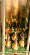
The first photograph shows an eight channel source arrangement. Each source can be independently addressed and the excitation duty factor and current levels controlled. In addition, the circuitry provides current feedback monitoring to ensure that source failures can be identified. Individual optical fibre-source alignment is carried out using special tooling.
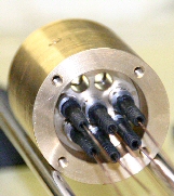
Optical spectrum filtering of the excitation sources is carried out using a high extinction ration bandpass filter. However, due to the thickness of this component, placement at the source would result in excessive optical power losses (circa 20dB). An inline fibre to fibre collimation module was therefore designed, the second image, which reduced optical losses to a more manageable 4dB.
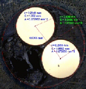
When dealing with larger core optical fibres (200 microns and above) it is usual to see significant variations in transmitted optical signal levels due to component and fibre misalignments, image 3. It is therefore essential that the measurement system design can accommodate these variations. This is accomplished in this instrument via careful source control, digitally controlled amplifier gain stages, time constant integration control and APD voltage setting.
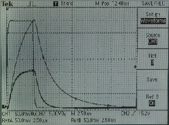
The rightmost images shows the range of quenching signal measured by the system. The square pulse represents the LED excitation pulse, the large trace the unquenched (100%) nitrogen signal and the smaller trace the quenched oxygen (~21%) signal.
If you wish to find out more about this application of optical fibre sensing please contact Mr Stuart Murray.